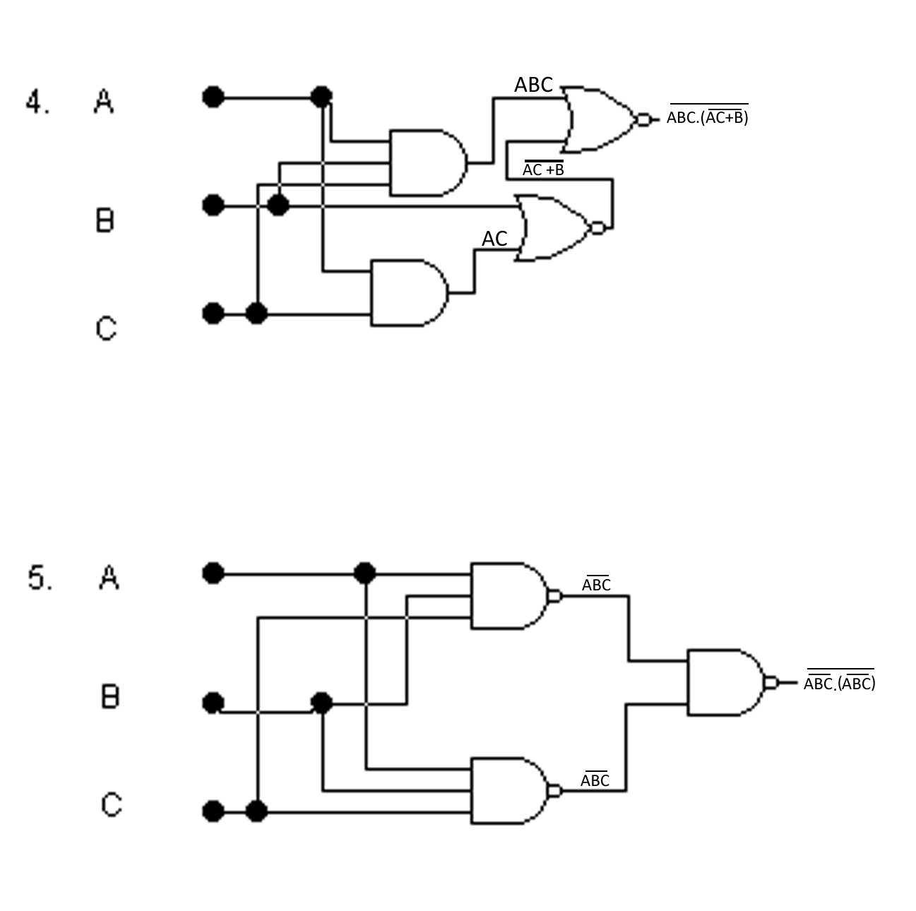
A Logic Gate Circuit
Logic gates instrumentation tools Cmos logic circuit Logic gates circuits digital part small versatile blocks building volts nuts
Wiring Diagram with ConceptDraw PRO
Xor nand xnor logic nor vhdl simulate input engineersgarage verify dummies wiring inverter scosche inputs The diagram of the logic gate circuit is given below. the output y of Cdot represented
Logic gates gate circuits diy nand basic verilog microchip starting electrical stack buffers source original components example
Digital breadboard system logic gates circuits integrated electronicsLogic transistor logika gerbang circuits gatter ttl rtl inputs transistors transistoren nand arduino tutorials fungsi rangkaian cmos verification boolean expression Logic gate symbols diagram electrical wiring elements engineering diagrams conceptdraw library schematic drawing alu boolean examples bit template pic elementGate logic circuit study.
Wiring diagram with conceptdraw proVhdl tutorial – 5: design, simulate and verify nand, nor, xor and xnor Logic gate circuit ~ study with prandanaSmall logic gates — the building blocks of versatile digital circuits.

Logic gates circuit
Cmos logic circuit design for and and or gateDigital electronics: logic gates Logic equivalent instrumentationtools connected energize parallel normally actuatedLogic gates and logic circuits.
11+ logic gates circuit diagram .


Logic Gates Instrumentation Tools

CMOS Logic Circuit Design for AND and OR Gate - YouTube

VHDL Tutorial – 5: Design, simulate and verify NAND, NOR, XOR and XNOR

logic gates circuit - Theory articles - Electronics-Lab.com Community

Wiring Diagram with ConceptDraw PRO

11+ Logic Gates Circuit Diagram | Robhosking Diagram

logic gate circuit ~ Study with Prandana

Digital Electronics: Logic Gates - Integrated Circuits Part 1 - YouTube

The diagram of the logic gate circuit is given below. The output Y of
